
Buildings as Code in Every Phase
A practical demonstration of a new approach to building design

In this blog post, we will take an in-depth look at the process of using Buildings as Code™ to define your building design. We will illustrate how Buildings as Code can be applied to every phase of the building design process and demonstrate the advantages that this approach offers throughout the design process.
Designing a building is a long and complicated process. Over the decades since AutoCAD’s release in 1982, many specialized software tools have cropped up in an attempt to aid in that complexity. Building information modeling (BIM) is a general term for the most recent generation of these tools which is commonly associated with platforms such as Revit, ArchiCAD, and Microstation. Programming environments like Dynamo Studio expand what’s possible with these tools by enabling architects to design solutions based on computational workflows. The output data, geometry, and presentation of these tools are often marked up and critiqued between team members in further external platforms like Bluebeam Revu. Throughout the life of a project, all of these tools may be used to accomplish various objectives in each phase, not to mention Excel, PlanGrid, Asana, Slack, email, and more. However, as the pace and intricacy of modern building design increases, we regularly encounter the limitations of even the most capable BIM tools. While each offers minor automation improvements to the building design process, the complexity of modern buildings is already quickly outgrowing them.
Anyone who has worked on a large-scale building project has experienced the frustration of dealing with multiple sources of truth and the difficulty of ensuring consistency across all deliverables. Imagine that you are the lead engineer on a data center project that has proceeded up through design development as a two-building scheme, but the cost estimate comes back so high that the entire scheme must be redeveloped as one building. While unforeseen obstacles like this are common in the building design process, even state-of-the-art BIM tools are ill-equipped to handle them. Modern BIM tools are not sophisticated or streamlined enough to manage these complex, real-life situations, and they can even compound the time and money lost trying to find solutions to them.
The AEC industry is long overdue for a transformation to the building design process that will render it capable of scaling with the needs of modern large-scale buildings. At TEECOM R&D, we are working directly with architects and engineers to develop Buildings as Code™, an alternative to the status quo of building design. Rather than create another stopgap tool to meet each new challenge surfaced by modern building design, Buildings as Code reimagines the design process and is designed to advance with building design’s emerging needs — not just keep up with them.
In this blog post, we will build out a two-building data center from scratch as a case study to demonstrate how to define building design in code with Buildings as Code. We’ll iterate on the design of our data center in every phase, from schematic design to construction administration.
What is Buildings as Code?
Buildings as Code (BaC) is a collection of libraries that allows designers to describe building design using structured data types and algorithmic expressions. BaC applies the same approach used to deliver software applications to large-scale building design. With BaC, architects and engineers use an easy-to-learn domain-specific language (DSL) to express the minimal description of their building design in code.
F# Programming Language
BaC's DSL is built on top of the F# programming language. F# is a functional-first language built on the .NET platform. F# allows types to be defined more concisely and expressively than in other statically-typed languages like C#, C++, or Java, and thus is more approachable for domain experts who are new to programming.
Let’s take a closer look at types in F#. Say we are developing a DSL to describe a farm in the countryside. Every farm needs animals, so we will define a new type Animal. We’ll use a discriminated union to define multiple cases under a single type.
 type Animal =
    | Cow
    | Sheep
    | Horse
The union cases above — Cow, Horse, and Sheep — express the different possible options for animals on our farm.
Record types allow us to define labeled fields on a type. Using records, we can express additional data about each of our animals.
type Cow =
    {
        weight: float
        spots: bool
        horns: bool
    }

type Sheep =
    {
        color: string
        fluffiness: float
    }

type Horse =
    {
        maneStyle: string
        maxSpeed: float
        shoeSize: int
    }
Records can have any number of data fields. The types of records fields can be primitive F# types like in the example above, or other custom types built out by the programmer.
We will see both discriminated unions and records frequently when we begin defining the elements of our data center below and rely heavily on this compact, expressive type definition syntax to express the components of our building design.
The BaC Paradigm
Buildings as Code supports an “information-first” paradigm for building design. By defining buildings in code, we can express both the geometric and non-geometric information of a building with complete clarity, and with good code hygiene, we completely disambiguate common sources of lost project information that arise from inscrutable Dynamo scripts, Bluebeam markups, Revit parameters, and more.
Further, by defining buildings in code, we prioritize the logical structure between building components rather than focusing merely on the resulting drawings. Buildings as Code allows designers to express the building design as a type system and centralize the design to a single definition in code from which all deliverables are automatically derived. This allows changes in the design to propagate to every deliverable, saving architects and engineers needless repetitive work of updating multiple sources of truth and guaranteeing consistency between all deliverables for a project.
Defining buildings in code also allows us to leverage the vast ecosystem of tooling that software developers use to support the most complex software applications in the world. With BaC, we can use version control to track changes to our design, employ programmable workflows to automatically generate deliverables from a single design definition, and write tests to ensure that functional requirements for the building are met with every change.
Now, let’s dive into the design of our data center.
1. Schematic Design
The AIA describes the schematic design phase as the “development of graphic and written conceptual design solutions for owner/client’s approval.” The goal of the schematic design (SD) phase is to establish the look, feel, shape and size of the building. As the client and architect form a vision for the building, they explore many ideas and rapidly iterate through a wide range of design possibilities. The architect produces concept designs and basic plans based on the client’s needs and requirements of the project. Deliverables for SD typically include the building massing, basic floor plans, exterior elevations, wall sections, and preliminary 3D models.
Defining Design in Code
With Buildings as Code, the architecture and engineering teams work together to define data types that describe the building's spatial and functional components to create a shared mental model of the design.
In SD, we want to establish the general shapes and sizes of the buildings in the project. From the very outset, we will write code to express the schematic design of the data center.
We'll begin our design definition with a new type Building to represent the buildings in our project. So far, we know that there will be two buildings. Without yet knowing anything about the contents of the buildings, we can write out the most basic possible expression of the Building type using a combination of a discriminated union and a record.
module Building =
    type Index =
        | One
        | Two

    type Building<[<Measure>] 'u> =
        {
            index: Index
        }
Here, we have created two new types:
The
Indexdiscriminated union which has two cases,OneandTwo, each identifying one of the buildings on the site for this schemeThe
Buildingrecord which has anindexfield of the typeIndex. The'uis a type parameter that will later indicate the units of the building's measurements. Unit type parameters allow us to generalize across imperial and metric unit systems, allowing an entire design to be easily transplanted into a different jurisdiction that requires record drawings with different units.
With that, we have created our first two types in Buildings as Code. We will build upon our foundational Building type throughout each phase of the project to eventually include walls, a floor, a roof, server rows, and data center equipment.
All components of our design can be templated in the same manner as above. Buildings as Code has many built-in types available for use across projects and allows designers to define their own, custom types freely.
Using our new Building type, let’s define another type Site that contains a minimal description of the project site in code.
module Site =
    type Site<[<Measure>] 'u> =
        {
            name: string
            buildings: Building.Building<'u> array
        }
Here we have defined a new record type Site that contains fields for the site’s name and an array of buildings contained within the site. New types can be built from existing types — as exemplified above, the type of the buildings field is the Building type that we defined a moment ago.
Let's expand upon our Building definition and add some walls. Using the built-in Wall type provided by BaC, we can extend our Building type to include both index and walls fields.
type Building<[<Measure>] 'u> =
    {
        index: Index
        walls: Wall.Wall<'u> array
    }
Functions
Our data center will contain two buildings, one larger and one smaller. We can define the following function wallDims which returns a wall with the desired dimensions depending on which building index is passed as an argument.
let wallDims buildingIndex =
    match buildingIndex with
    | One ->
        {
            Wall.width = 30.0<m>
            Wall.depth = 0.3<m>
            Wall.height = 16.0<m>
        }
    | Two ->
        {
            Wall.width = 20.0<m>
            Wall.depth = 0.3<m>
            Wall.height = 16.0<m>
        }
This function creates a new instance of a wall for the given building with the appropriate width, depth, and height.
Now that our building has some geometry, we are almost ready to generate an initial 3D model of our site. To render our abstract building definition as a 3D model, we will need to call a helper function that turns our design definition into model elements.
let elements (b: Building<_>) =
    let walls = b.walls |> Array.collect (Wall.toElement b.basis)

    [| yield! walls |]
Given an instance of our Building type, the elements function above gets the walls for that building and converts them into elements to be rendered in a 3D model. For wall elements, BaC provides a helper function Wall.toElement that we can use. Designers can also define their own implementations for converting custom building components into 3D elements at any time.
With that, we have everything we need to view our initial site definition as a 3D model.

We have now generated a 3D model of our design that is 1:1 with our building definition in code. BaC makes it easy to view our 3D model in a web browser on desktop, laptop, or mobile. On the left, we have the larger of our two buildings, and the smaller building is on the right. We could easily change the dimensions in our wallDims function if desired and automatically regenerate a new 3D model in moments.
Automatically generating deliverables
Above, we generated a 3D model of our site with very little overhead. But that's not all — once we have a minimal definition of the building in code, BaC can adapt this definition to any number of output formats, including not only 3D models in multiple formats including IFC and Revit, but also 2D elevations and bills of materials.
All deliverables are generated in mere seconds so that the client and architect are freed up to focus on the conceptual design of the building. Furthermore, preliminary versions of construction documents that are typically not created until the construction documents phase can be generated as early as SD with no additional overhead.
Iterating on Design
Now that we’ve walked through the process of adding building elements in detail, we can rapidly iterate on our schematic design and complete our preliminary 3D models.
Our buildings are going to need a floor and a roof. In the same way that we added walls, let’s add floor and roof fields to our Building type.
type Building<[<Measure>] 'u> =
    {
        index: Index
        walls: Wall.Wall<'u> array
        floor: Floor.Floor<'u>
        roof: Roof.Roof<'u>
    }
We can write functions to calculate the dimensions of our floor and roof components based on the wall dimensions of the given building.
let floorDims index =
    let wall = wallDims index

    {
        Floor.width = wall.width
        Floor.depth = wall.width
        Floor.height = wall.depth * 3.0
    }

let roofDims index =
    let wall = wallDims index

    {
        Roof.width = wall.width - wall.depth
        Roof.depth = wall.width - wall.depth
        Roof.height = wall.depth
        Roof.elevation = wall.height * 0.8
    }
These functions exemplify how BaC expresses relationships of components within buildings, rather than treating components as discrete and separate.
To see the new floor and roof in our 3D model, we simply add them to our Building.elements function alongside the walls.
let elements (b: Building<_>) =
    let basis = b.basis

    let walls = b.walls |> Array.collect (Wall.toElement basis)
    let floor = b.floor |> Floor.toElement basis
    let roof = b.roof |> Roof.toElement basis

    [| yield! walls; floor; roof |]
In just moments, we automatically regenerate a new model to visualize our changes.

With this, we have a schematic design of the exterior of our building defined in code and the corresponding deliverables. In the coming phases, we will see how we can automatically generate other deliverables alongside our 3D model, such as 2D elevations and bills of materials.
Git
For the duration of the project, our building definition will be managed through repositories in Git. Git is a distributed version control system that tracks the full history of changes to any set of files. Git is an extremely popular tool among programmers, writers, and others, used by the smallest teams to the biggest tech companies in the world to manage codebases and coordinate parallel tracks of development within teams.
Version control
In SD, we established the basis of our building design. As our design rapidly evolves throughout the remaining phases, it will become increasingly important to track every change along with who made it, when, and why.
Version control is a tool designed exactly for this purpose. Version control captures every revision to our code and corresponding deliverables in a commit log. This log tells the “story” of the design up to a given point in time, allowing architects and engineers to easily trace every design decision back to its root. Commit logs contain the history of every change along with the author, date, and description of the reason for the change.

With version control, architects and engineers can reference a historical version of the design and, if desired, revert the project to that state at any time. Managing the building definition through Git allows designers to make changes more safely, with the assurance that everyone is working on the latest version of the design and that past revisions can always be recovered.
With a basic definition of our building design defined in code and a remote repository initialized on Git to manage it, let’s move on to the design development phase and continue to iterate on our design using BaC.
2. Design Development
After SD, we move on to the design development (DD) phase. The AIA defines DD as when the “project’s schematic design is refined, including designing details and selecting materials. This step occurs after the owner/client has approved the schematic design.” In DD, the architect revises initial drawings from the SD phase based on feedback from the client. All aspects of the preliminary design are expanded to include full detail. Engineering teams begin work on the heating, electrical, ventilation, and energy systems for the building, and construction materials are selected. At the end of DD, both the interior and exterior designs of the building are finalized. Deliverables for DD typically include interior elevations, reflected ceiling plans, and details and finishes.
Iterating on interior design
With the general massing of the project defined, let’s add some more detail to the interior of our buildings and bolster their structural integrity by adding trusses to our roofs. After SD, we received framing calculations from our structural engineer that we can use to define a truss with the appropriate capacity.
To encode trusses into our building design, we’ll define a new type Truss that depends on another new type Web and the existing Roof type.
type Web<[<Measure>] 'u> =
    {
        thickness: float<'u>
        width: float<'u>
        height: float<'u>
        angle: float
    }

type Truss<[<Measure>] 'u> =
    {
        depth: float<'u>
        width: float<'u>
        thickness: float<'u>
        webbing: Web<'u>
        roof: Roof.Roof<'u>
    }
Here again, we see that defining buildings in code allows us to describe design in terms of the relationships between components. Expressing design intent this way eliminates the resource-intensive task of updating multiple sources of truth when design changes occur. Instead, changes to one object flow through to each object it relates to, ensuring congruity between all related objects.
The Truss type we defined above has a Roof field. By referencing a truss’s roof, we can calculate the desired measurements for the truss based on the dimensions of its hosting roof.
let truss (roof: Roof.Roof<_>) : Truss.Truss<_> =
    let (webbing: Truss.Web<m>) =
        {
            thickness = 0.25<_>
            width = 0.25<_>
            height = 1.5<_>
            angle = 45.0
        }

    {
        height = 2.5<_>
        width = roof.width - 0.5<_>
        thickness = 0.5<_>
        webbing = webbing
        roof = roof
    }
Here, we create a durable link between the length of the trusses and the dimensions of the roof which eliminates the need for the structures team to wait for updates to an architectural background. The dimensions are logically linked in the project, and so we link them programmatically in our code.
We add the trusses to our elements function and instantaneously regenerate the model to see them rendered in 3D.
let elements (b: Building<_>) =
    let basis = b.basis

    let walls = b.walls |> Array.collect (Wall.toElement basis)
    let floor = b.floor |> Floor.toElement basis
    let roof = b.roof |> Roof.toElement basis
    let trusses = b.roof |> truss |> Truss.many 5 basis

    [| yield! walls; floor; roof; trusses |]
Equipment design
Let's now shift our focus to building out the server rows of the data center. First, we add a new rows field to our Building type. The type of this field, Row.Row, is provided by BaC.
type Building<[<Measure>] 'u> =
    {
        index: Index
        walls: Wall.Wall<'u> array
        floor: Floor.Floor<'u>
        roof: Roof.Roof<'u>
        rows: Row.Row array
    }
For the purposes of our data center, a Row can be thought of as a collection of racks and vertical cable managers (VCMs). There are multiple rack styles built into BaC that are available for use in any project and designers can also define their own custom racks or other row items at will.
Our client is a hyper-scale operator with specific equipment requirements for this site. We'll create a fully custom equipment module specific to this project to represent each of these possible equipment options.
module Equipment =
    type PatchPanelFunction =
        | Interpod
        | Intrapod

        override z.ToString() =
            match z with
            | Interpod -> "Interpod"
            | Intrapod -> "Intrapod"

        member z.size =
            match z with
            | Interpod
            | Intrapod -> 1

        member z.color =
            match z with
            | Interpod -> Color.hex "#f9ceee"
            | Intrapod -> Color.hex "#e4d3ea"

        member z.name= $"Patch Panel ({z})"

    type Equipment =
        | PatchPanel of PatchPanelFunction

        interface ISizeable with
            member z.size =
                match z with
                | PatchPanel f -> f.size

        interface Color.IColorProvider with
            member z.color =
                match z with
                | PatchPanel f -> f.color

            interface ICommonName with
                member z.name =
                    match z with
                    | PatchPanel f -> f.name
Our new Equipment module defines a new type Equipment of the same name. To start, our equipment type has only one option, PatchPanel. PatchPanels have an associated PatchPanelFunction of which there are two cases, Interpod (trunks) or Intrapod (patching).
BaC defines an interface that custom equipment types must adhere to in order to be considered valid. Adhering to this interface means that any client-specific equipment can be used with library types to populate racks and rows, generate bills of materials, and more. The interface requires that custom equipment types specify a size, color, and name. Our custom equipment types above implement a member for each of these attributes, so the equipment types we added fully adhere to the interface required by BaC. We can add any number of new cases to represent more equipment options as long as they also implement a size, color, and name member.
type Equipment =
    | PatchPanel of PatchPanelFunction
    | LeafSwitch
    | SpineSwitch
    | Breakout
    | DCSystemsConsole
    | DCSystemsSwitch
    | Rectifier
    | PodSwitch
    | BatteryBackup
    | DistributionPanel

    interface ISizeable with
        member z.size =
            match z with
            | PatchPanel f -> f.size
            | LeafSwitch
            | SpineSwitch -> 8
            | Breakout
            | DCSystemsConsole
            | DCSystemsSwitch
            | Rectifier -> 1
            | PodSwitch -> 16
            | BatteryBackup
            | DistributionPanel -> 2

    interface Color.IColorProvider with
        member z.color =
            match z with
            | PatchPanel f -> f.color
            | LeafSwitch -> Color.hex "#c1f0fb"
            | SpineSwitch -> Color.hex "#dcf9a8"
            | Breakout -> Color.hex "#ffebaf"
            | DCSystemsConsole -> Color.hex "#a8e6cf"
            | DCSystemsSwitch -> Color.hex "#dcedc1"
            | Rectifier -> Color.hex "#ffd3b6"
            | PodSwitch -> Color.hex "#ead3de"
            | BatteryBackup -> Color.hex "#d5e3f0"
            | DistributionPanel -> Color.hex "#e0cdff"

    interface ICommonName with
        member z.name =
            match z with
            | PatchPanel f -> f.name
            | LeafSwitch -> "Leaf Switch"
            | SpineSwitch -> "Spine Switch"
            | Breakout -> "Breakout"
            | DCSystemsConsole -> "DC Systems Console"
            | DCSystemsSwitch -> "DC Systems Switch"
            | Rectifier -> "48V DC Rectifier"
            | PodSwitch -> "Pod Switch"
            | BatteryBackup -> "48V DC Battery Backup"
            | DistributionPanel -> "48V DC Distribution Panel"
Let's continue to flesh out our interior design with server racks to host this equipment in our data center. In the next section, we will build out the rows for our two buildings in parallel to demonstrate the role of branches in Git.
Branches
Branches are a feature of Git that isolates in-progress work from the main design. As the client and architect experiment with potential designs in DD, branches allow them to easily manage many different design options. Using branches, designers can explore many possibilities without committing any formal changes to the design.
In DD, engineering teams are brought on to begin work on various systems within the building, including heating, electrical, ventilation, and more. This is an ideal use case for branches. Branches enable simultaneous, nonlinear work on the same design so that multiple teams can work in parallel on different aspects of a project. Git automatically reconciles the differences between the main branch and development branches when a development branch is merged. In the event that multiple teams make conflicting changes to the design, Git provides an easy-to-use interface for resolving integration conflicts.
To demonstrate the use of branches in Git, we'll build out the server rows for each building on separate branches.
Server row design
For our project, we'll have one engineer design the server rows for Building One and another engineer for Building Two. The engineer on Building One creates a new branch called design-development-building-1, and the engineer on Building Two creates design-development-building-2.

Our two engineers begin designing the rows of their respective buildings in parallel. Below, we see the code that each engineer commits to their respective branch.
branch: design-development-building-1

let buildingOneRowItems =
    let twoPostRack = Array.empty |> Rack.twoPost 51 |> Rack
    let fourPostRack = Array.empty |> Rack.fourPost 51 |> Rack
    let vcm = RowItem.VCM(51, 10)

    seq {
        yield! Seq.replicate 3 twoPostRack
        yield! Seq.replicate 43 fourPostRack
        yield! Seq.replicate 3 twoPostRack
    }
    |> Seq.interweave vcm
branch: design-development-building-2
let buildingTwoRowItems =
let twoPostRack = Array.empty |> Rack.twoPost 51 |> Rack
let fourPostRack = Array.empty |> Rack.fourPost 51 |> Rack
let vcm = RowItem.VCM(51, 10)
seq {
yield! Seq.replicate 3 twoPostRack
yield! Seq.replicate 27 fourPostRack
yield! Seq.replicate 3 twoPostRack
}
|> Seq.interweave vcmThe initial row items definition for each building includes empty racks and VCMs with no equipment. Because Building One is larger, it has 43 four-post racks per row while Building Two has 27 four-post racks per row.
Below, the rows function on each branch specifies that Building One has 10 rows of buildingOneRowItems and Building Two has 5 rows of buildingTwoRowItems.
branch: design-development-building-1

let rows index =
    match index with
    | One ->
        [ 1..10 ]
        |> Seq.map (fun i ->
            let name = $"Building 1 - Row {i}"

            Row.buildingOneRowItems
            |> Row.row name
        )
        |> Array.ofSeq
    | Two -> Array.empty
branch: design-development-building-2
let rows index =
match index with
| One -> Array.empty
| Two ->
[ 1..5 ]
|> Seq.map (fun i ->
let name = $"Building 2 - Row {i}"
Row.buildingTwoRowItems
|> Row.row name
)
|> Array.ofSeqAutomated workflows in GitHub
In GitHub, designers can create automated workflows that automatically regenerate all deliverables every time a design change is pushed to Git. After both engineers push their changes to their respective branches, automated workflows kick off and generate a 3D model for each in just moments.

We can create many automated workflows to generate any number of deliverables from a single change in code. For example, say our engineers have created two other automated workflows that run on every change: one for generating 2D elevations, and another for generating BOMs. They’ll see the automatically generated 2D elevations and BOMs in their Git diff:


With Buildings as Code, a single change to the definition of the building in code automatically propagates to all deliverables to guarantee consistency between deliverables and eliminate needless repetition. Further, the instantaneous feedback of automatically generated deliverables makes it easy for architects and engineers to understand the impact of their design choices throughout the building design process.
In GitHub, we can see the changes for each branch reflected in their respective diff.

design-development-building-one branch from adding initial server rows to Building One
design-development-building-two branch from adding initial server rows to Building TwoWith our initial empty racks for both buildings defined, let's finish out the DD phase by adding equipment to our racks.
branch: design-development-building-1

let buildingOneRowItems =
    let twoPostRack =
        Array.empty
        |> Rack.twoPost 51
        |> Rack.insertNAt 10 1 (PatchPanel Interpod)
        |> Rack.insertNAt 10 11 (PatchPanel Intrepid)
        |> Rack

    let fourPostRack = Array.empty |> Rack.fourPost 51 |> Rack
    let vcm = RowItem.VCM(51, 10)

    seq {
        yield! Seq.replicate 3 twoPostRack
        yield! Seq.replicate 43 fourPostRack
        yield! Seq.replicate 3 twoPostRack
    }
    |> Seq.interweave vcm
On the design-development-building-1 branch, we add passive equipment to the two-post rack definition.

These patch panels are immediately evident in the regenerated 2D elevations of the row shown above.
The client has specified for this project that each row has several duplicate racks with the same arrangement of equipment. We can define a single definition for each unique rack and reuse it as needed.
let dcSystemsRack =
    Array.empty
    |> Rack.fourPost 51
    |> Rack.insertNAt 8 10 Breakout
    |> Rack.insertNAt 4 22 DCSystemsSwitch
    |> Rack.insertAt 26 LeafSwitch
    |> Rack.insertNAt 2 39 DCSystemsConsole
    |> Rack.insertNAt 4 43 (PatchPanel Interpod)
    |> Rack
let podSwitchRack =
    Array.empty
    |> Rack.fourPost 51
    |> Rack.insertAt 19 BatteryBackup
    |> Rack.insertAt 21 Rectifier
    |> Rack.insertAt 35 PodSwitch
    |> Rack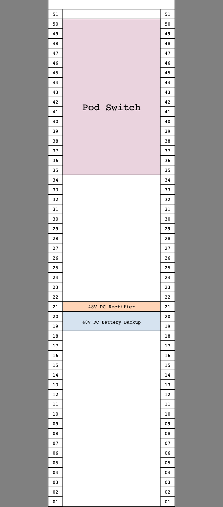
let distributionPanelRack =
    Array.empty
    |> Rack.fourPost 51
    |> Rack.insertSpacedNAtWithSpacing 6 16 1 DistributionPanel
    |> Rack
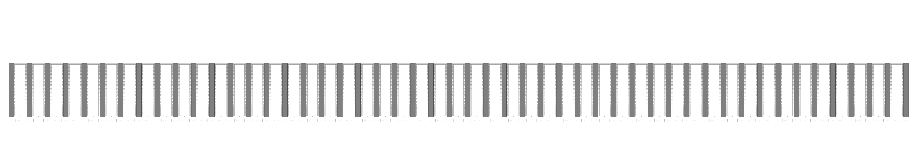
We can use these rack definitions in place of the empty four-post racks from our initial row items definition and fill out the entire Building One row with equipment.

The engineer working on Building Two can use the same common rack definitions, or different ones as needed, to build out the rows for their building.


We can visually inspect the 2D elevation and 3D model to see that they are exactly 1:1 with each other, as they are both derived from a common row definition in code.
When both engineers have completed the design for their respective buildings, they can request a review from their colleagues in GitHub. Once all checks pass, they merge their development branches into the main branch.

With each development branch merged into the main branch, the changes from both are now reflected in the new 3D model.

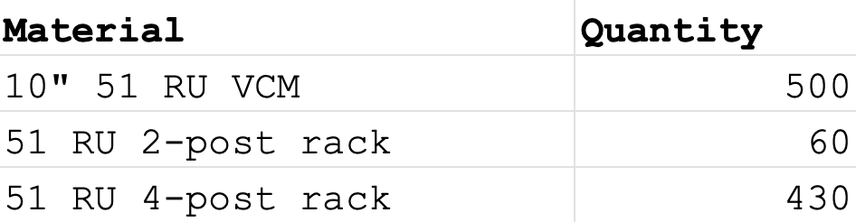
The elevations for this project are generated on a per-row basis, so we do not see changes to the elevations, but we do see that the row items and equipment of both buildings are reflected in the updated BOM.

Now that our design is complete for both buildings and their definitions in code are committed to the main branch of our repository, we are ready to move on to the next phase of the project — construction documents.
3. Construction Documents
The construction documents (CD) phase is the largest phase of the building design process. Per the AIA, the deliverables for this phase are “the written and graphic instructions used for construction of the project,” and these documents “must be accurate, consistent, complete, and understandable.”
In CD, the design of the building is finished and the goal is to produce multiple drawing sets and specifications that detail the entire construction process. Deliverables for this phase include a construction document (CD) set and a filing set.
The CD set is a collection of technical drawings that serve as the general contractor’s manual for the construction of the building. Typically this includes interior and exterior elevations, building and wall sections, a site plan, foundation and floor plans, a framing plan, a roof plan, electrical and lighting plans, final specifications for construction details, materials, and appliances, and door and window schedules.
The filing set is the drawing set that is submitted to the Department of Buildings (DoB) which the DoB must approve before issuing a permit. The DoB reviews the drawing set to determine whether it complies with building codes, zoning laws, and other state and local requirements.
Cutting costs and time in CD
While CD is traditionally the largest phase in the building design process, with BaC, engineers can drastically reduce the amount of time and effort required in this phase. BaC generates early versions of construction documents from the very beginning of the design process, so by the CD phase, many iterations of all construction documents have already been generated throughout every change to the design. This begins in SD, the very first phase, with zero additional overhead from the design team. All that is required by the time of CD is that the architects and engineers review and approve the final versions of documents that they've already seen many times over.
Incorporating last-minute changes
Ideally, the building design should be finalized by SS and no further design changes should be made in later phases including CD. Unforeseen conditions arise in many projects, though, and in the event that changes to the design changes are necessary, BaC enables these last-minute changes to be made frictionlessly, even late in a project.
Say our client just came back to us with bad news: the budget for our data center project has been slashed. In fact, the budget cuts are so drastic that we only have enough money to construct one building rather than two. To keep the project from going under, we must find a way for our design to include only one building that accommodates all of the server rows from both original buildings.
Following the traditional building design process, this would be extremely challenging to address in CD. Without much time to make these major design changes and considering all of the money and labor that has already been sunk into the project so far, this would be prohibitively expensive to remedy so late in the game.
With Buildings as Code, however, last-minute changes can be accommodated with ease.
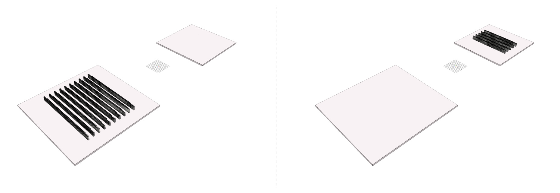
Revisiting our Building definition, we remove the Two case from the Index type and expand the dimensions of our One-indexed building to accommodate the server racks of both original buildings.

Instantly, we regenerate the 3D model to reflect the changes.


We can also see the changes reflected in our automatically regenerated 2D elevations, which show all server rows from both buildings.

With only a few lines of code changed, we have completely transformed the design of our project and come in under the new budget. And in moments, we have generated updated versions of the deliverables required to complete CD.
Functional tests
As final deliverables are generated in CD, architects and engineers must ensure that the design meets all functional requirements of the building. BaC allows engineers to express these functional requirements as tests that must be passed before design changes are approved. Even after a big change like combining two buildings into one, we can rest assured knowing that our design remains sound by passing the tests in our test suite. For example, the test below ensures that the correct number of patch panels is present within our site.
[<Test>]
let ``patch panel count for the site is correct`` () =
    let patchPanels =
        Main.site
        |> Query.equipmentOfSite
        |> Query.every Equipment.EquipmentKind.PatchPanel

    let patchPanelCount = patchPanels |> Query.toList |> List.length

    let expectedInterpodCount = 960
    let expectedIntrapodCount = 900
    let expectedTotal = expectedInterpodCount + expectedIntrapodCount

    patchPanelCount |> shouldEqual expectedTotal
BaC is platform-independent, so whether your code is managed through GitHub or another distributed version control system, designers can flexibly configure their repositories such that changes to the main branch can only be merged after all tests have passed.
4. Construction Administration
Construction administration (CA) is the final phase of the building design process. The AIA describes CA as tasks including “facilitating project communication, maintaining project records, reviewing and certifying amounts due contractors, and preparing change orders.” In this phase, the building is constructed and the majority of the remaining work is in the hands of the general contractor with the guidance of the CD set. The architect and engineers may periodically visit the job site to check in on progress and ensure that the construction aligns with the plans per the architectural design intent.
Change orders
In CA, any changes to the design or scope of work per the project contract must be addressed through change orders. These may arise as a result of unforeseen conditions, client changes to the project, shipping delays, and so on. Change orders can add hundreds of thousands of dollars in unanticipated construction costs and it can be challenging to assess whether a change order is even possible. The client, architect, and engineers must undertake the difficult task of evaluating the cascading effect of the change order, and some changes cannot be absorbed this late in the project.
Buildings as Code can reduce the number of potential causes for change orders. Because BaC derives all deliverables from a single building definition, it guarantees that all deliverables are consistent and eliminates incongruent CD sets as a source of error that would necessitate a change order.
If a change order is necessary, BaC can facilitate the process of addressing it as well. As we saw in the CD phase, BaC makes it easy to change even fundamental parts of a project design. Changes to the single design definition in code automatically propagate to all deliverables, which are automatically regenerated to reflect the updates.
Integrating with third-party systems
While BaC replaces many of the tools that are currently used in the design process, it also offers the ability to integrate into more specialized tools where desired. BaC is a software platform that is built for extensibility and is straightforward to integrate with APIs for document tracking, cost management, and more.
Conclusion
Throughout the process of creating our test data center, we saw the flexibility of BaC and made use of many built-in abstractions from the BaC library. We also created several types and abstractions of our own. Due to budget constraints, we ended up designing multiple site layouts, which themselves could be repurposed or generalized into configuration options for a base design that can be used again in future projects.
If tomorrow we work with a client who does have the budget for a two-building data center, we will be in a position to leverage the work that we did on this project in our next project. Not only does each BaC project benefit from the abstractions built up in previous projects, but each project can also contribute to these reusable pieces and benefit the projects that come after it.
Buildings as Code is a revolutionary approach to building design that bridges the clarity, compactness, and consistency of software design with the complexity of building design. With BaC, architects and engineers use an easy-to-learn domain-specific language and gain access to a wide ecosystem of tools that support their work and empower them to iterate rapidly, safely, and collaboratively on their designs. BaC puts building information at the center of the design process and automatically handles all of the time-consuming work of generating and updating deliverables while ensuring consistency between them and tracking the full history of revisions to the design.
Rather than bend over backward to conform to the limitations of modern building design tools, BaC reimagines how we manage building information to support the design process at every stage and effortlessly accommodate the growing complexity of modern, large-scale building design.